PIC Microcontroller Bootloader
21st January 2022
A bootloader is a small piece of code that resides at the start of the memory in a microcontroller that enables extra features. We have implemented a bootloader on the PIC microcontrollers we use in our development boards (PIC18F45K40). This bootloader enables the UART communications and allows the user to program the PIC with a single cable rather than using an expensive dedicated programmer every time you want to update the code.
If you’ve already got the bootloader on your PIC and you just want to know how to use it, skip to Step 2 – Using the bootloader.
Step 1 – Program the bootloader
You will need a PIC programmer if you want to load the bootloader onto a blank PIC, but once you have, the programmer is no longer needed. To do this you will need a pic programmer and the MPLAB X software, which we are assuming you have, as this is where you are probably writing your main code. You will also need our bootloader .hex file available here: https://github.com/machineshopuk/Bootloader
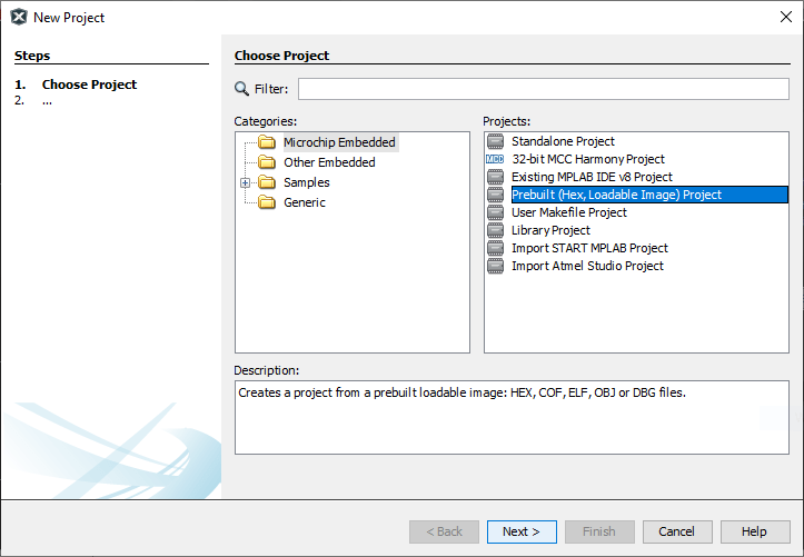
Make sure everything is connected like it would be if you are programming a PIC using MPLAB X. Then create a new project using a Prebuilt (Hex, Loadable Image) Project.
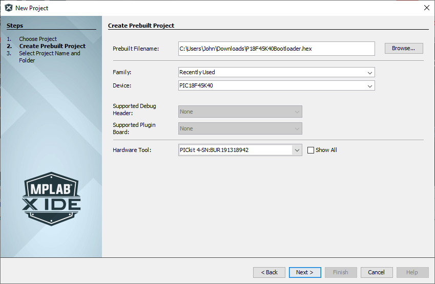
In the next window, select the .hex file you downloaded from Github. Under Device, type in PIC18F45K40. Then select your hardware tool, like we have below:
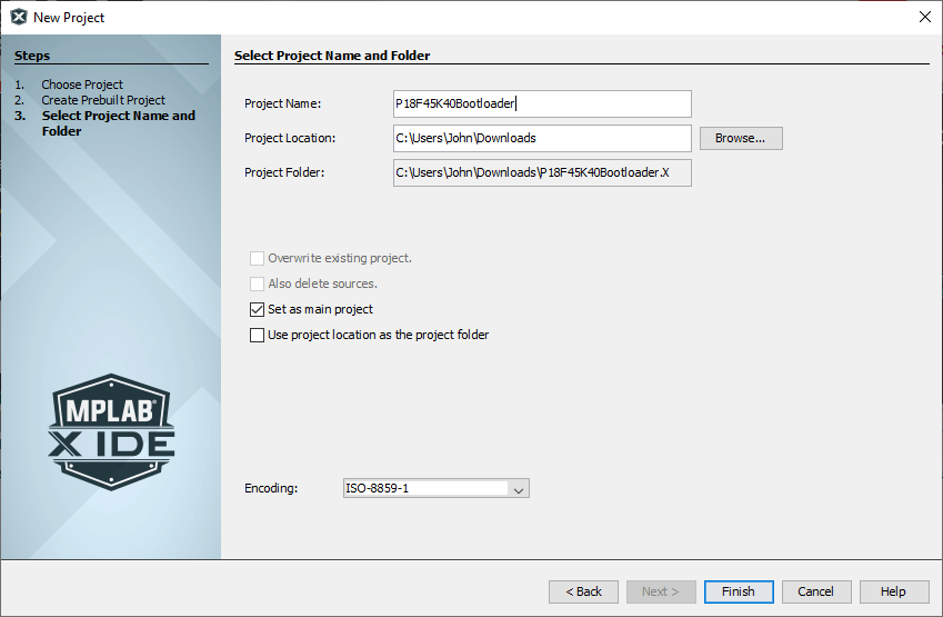
You can just click Finish on the next screen, or you can give it a name and different location if you prefer.
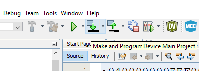
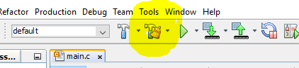
Now we are back in the main MPLAB X window we just need to program the PIC, to do this, make sure you board is plugged in and powered and click on the ‘make and program device’ button.
If you get a message that looks like this:
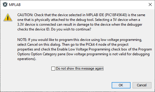
It’s basically just saying, you’ve selected a 5v device, make sure the device you’ve got plugged in is 5v. If you are using the PIC18F45K40 then it is 5v, so you can just click OK.
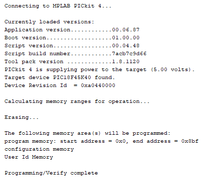
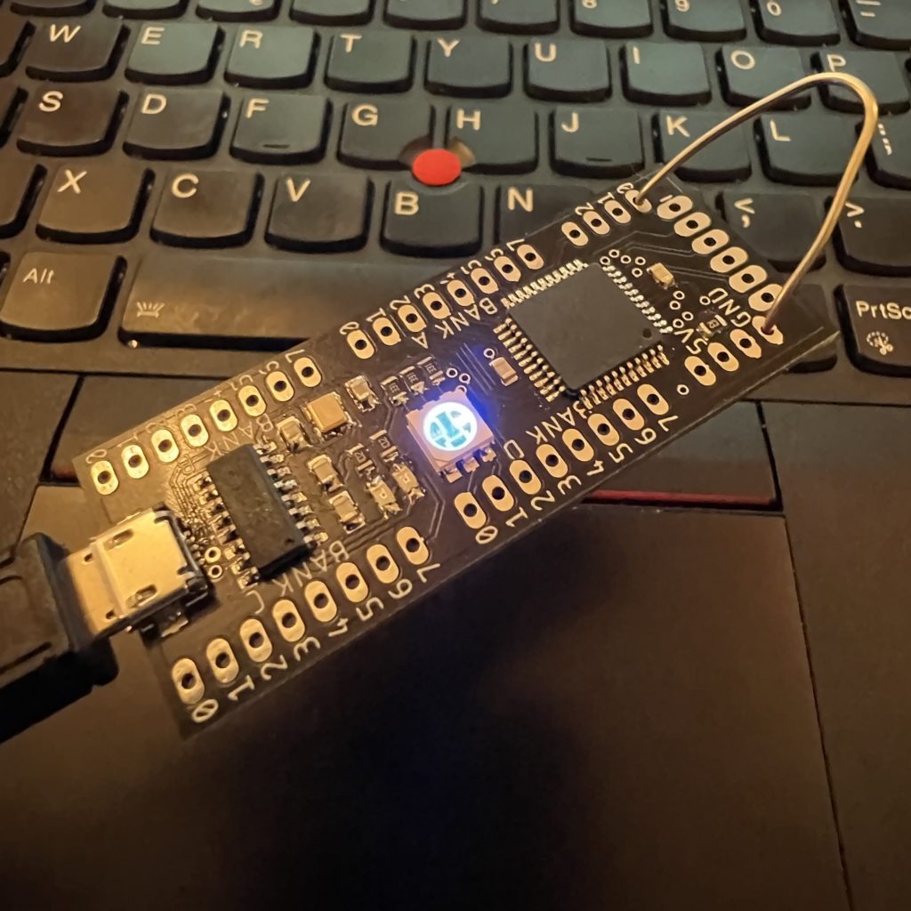
Once the PIC programs, it will pulse the LED connected to D0 and it will be running the bootloader. You can now disconnect the programming tool as this is no longer needed.
Step 2 – Preparing your application for the bootloader
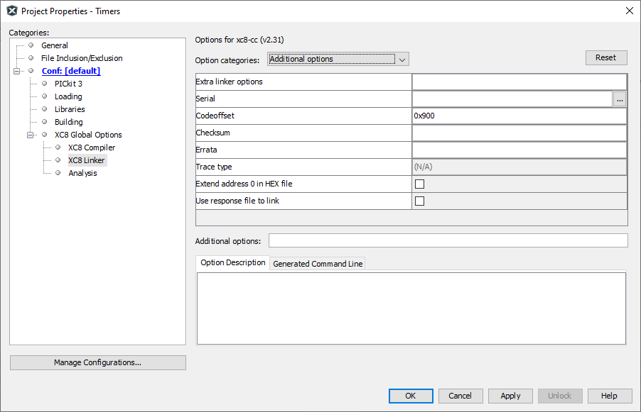
In order to program the PIC using the bootloader, you will need to make a little tweak to your project. In MPLAB X, open the project settings and got to XC8 Linker > Additional options and set the Code Offset to 0x900. This makes sure that the code is loaded into memory from address 0x900 onwards. Before this is the bootloader that needs to stay on the PIC for programming next time.
Now you can just build your project to create the .hex file
Step 3 – Programming using the bootloader
Now that the bootloader is programmed, flashing your code onto the PIC can be done with a simple micro USB cable into the micro USB port on the board.
There are two ways to enter the bootloader and be ready for programming. If you’ve just programmed the bootloader from step 1 then it will automatically enter the bootloader. The other way is to short pin E0 to GND and then power up the PIC. You’ll know if it is in the bootloader as it will pulse D0. You can now remove the short between E0 and GND.
You PC should recognise your PIC as a COM port. Now we can download your project to the PIC. To do this we are going to need Microchip’s unified bootloader host application, which you can get from here:
https://www.microchip.com/en-us/tools-resources/develop/libraries/microchip-bootloaders/8-bit
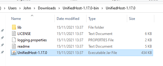
unzip the zip file you downloaded and open the Executable Jar File:
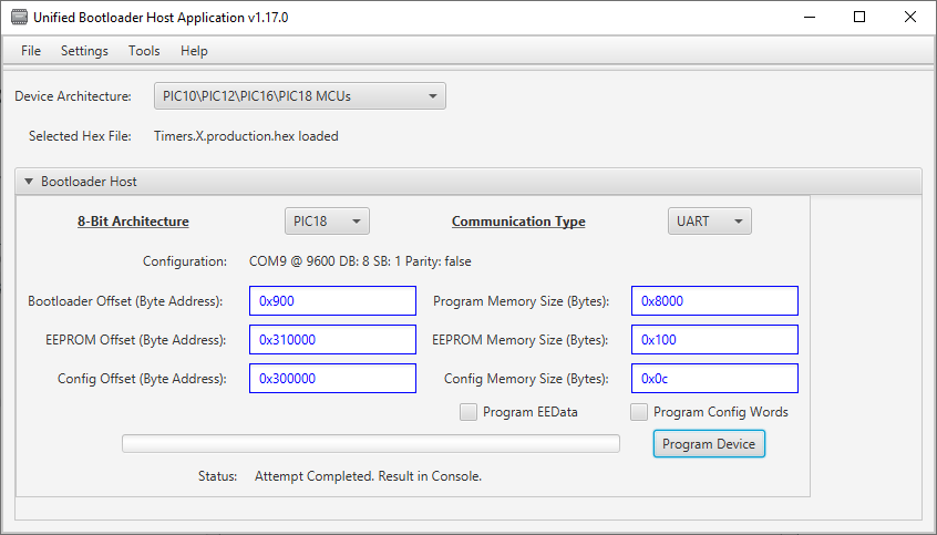
Once the program opens, you’ll need to configure it as we have below:
Pay particular attention to these options:
Device Architecture – PIC10/PIC12/PIC16/PIC18 MCUs
8-Bit Architecture – PIC18
Bootloader Offset – 0x900
EEPROM Offset – 0x310000
Program Memory Size – 0x8000
Config Memory Size – 0x0c
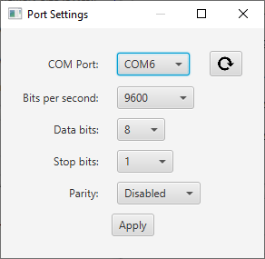
We need to tell the program which com port the PIC is connected to, to do this, click on Settings > Serial:
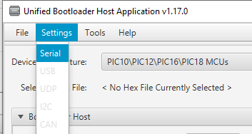
select the com port and leave everything else as default, then click Apply:
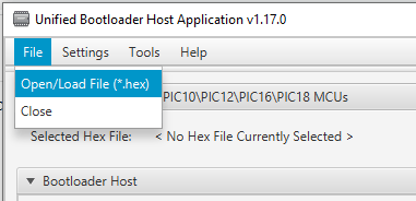
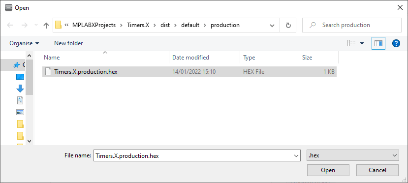
Now you just need to file your .hex file form your project. Ours was in the project folder under dist > default > production:
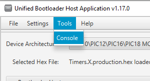
Once you’ve got all that setup, we can start the programming. We suggest opening the console to monitor the programming process by clicking on Tools > Console:
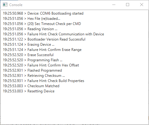
You should now see that your program is running. If it has gone back into the bootloader, make sure you have removed the short between E0 and GND and reset the power. Now everytime you power up your PIC it will bypass the bootloader and run your program.


