Raspberry Pi Pico Logic Analyzer
29th May 2021
Here I’m going to show you how to create a basic logic analyzer using a Raspberry Pi Pico. This project is basic in its functionality but goes over some good basics with the Raspberry Pi Pico including some microPython coding, reading inputs, controlling outputs and getting data out of the Pico. It occurred to me whilst I was teaching some of my students online about micro controllers that some of them did not have access to lab equipment like a logic analyzer at home and found it difficult to diagnose bugs in their microcontroller designs without access to things like logic analyzers, function generators and oscilloscopes. So I thought, everyones got a Raspberry Pi Pico (if not you can buy one here) why not use that? So I’ve set out designing some very effective electronics tools that won’t need too many extra components (if any) so makers and students can debug and test their designs without having to spends hundreds on lab equipment. Who knows, maybe their designs can plant them a contract or a job to give them the budget to buy some proper lab equipment like a proper logic analyzer.
Required Parts
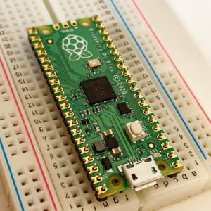
A Raspberry Pi Pico This is going to be the main brains of the project. We are going to utilise the multiple Digital inputs on the Pi Pico as well as the USB interface to communicate with the Pico
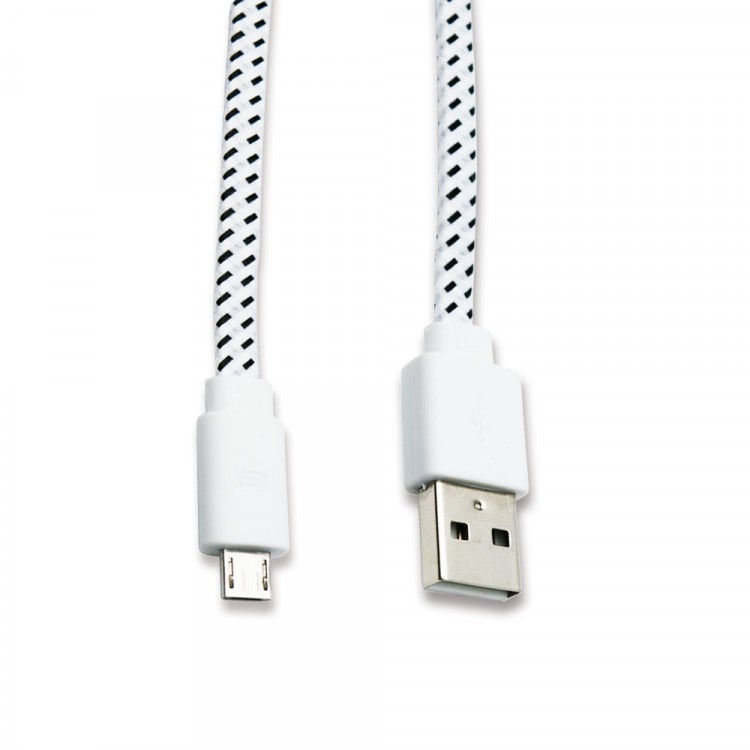
A Micro USB cable. Make sure this is a power and data USB cable as a lot of cheap cables are power only. The one we sell is power and data and is braided with strong connectors to make sure it lasts you a long time.
Some bits of wire (I used these Dupont wires) you could get away with any wire for this. I use theses male to male wires because its super easy to plug into the bread board and then reuse them on any other prototyping project I have. Again, I’ve used some cheap ones that have failed me, not ideal when you are trying to make test equipment. The ones we sell are excellent.

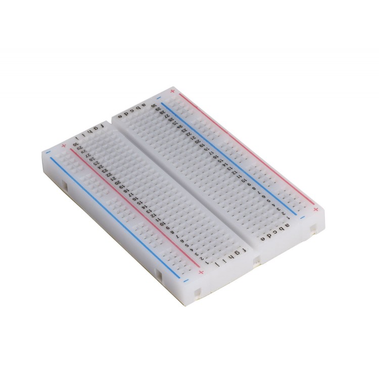
For ease you might want a small breadboard if you’ve soldered headers onto your Pico. This will allow you to reuse your pico for future projects without soldering wires onto it, plus you can plug in as many wires as you want to then and make it multichannel.
Basic Setup
Ok lets get on with it then. Plug your Pico into your computer and open up your favourite method of programming. Mine is to use PyCharm. If you want a quick setup guide on how to use the Pico with PyCharm Check out our blog post here or watch our YouTube video on it here.
Enter the following code to get us started, don’t worry we will get a little bit more advanced than this:
from machine import Pin  # import the Pin module from the machine library to read and write to the pins.
import time  # import the time library to create a delay.

led = Pin(25, Pin.OUT)  # setup pin 25 as an output, this is the onboard LED.
inputPin1 = Pin(0, Pin.IN, Pin.PULL_DOWN)  # setup pin 0 as an input with a pull down resistor.

while True:  # create a loop
    DigitalValue = inputPin1.value()  # Read the input pin.
    print("Digital Input:{}".format(DigitalValue))  # send the value of the pin to the computer.
    led.toggle()  # toggle the LED so we know the code is running.
    time.sleep(1)  # delay for 1 second.
Once you’ve typed up the code (or copy and pasted it in) then send it to the Pico and open the REPL, you may need to press CTRL+D to restart the program. You should see “Digital Input:0” if you don’t have anything connected to the pin. The value will read as 0 because we setup the input to have an internal Pull Down resistor which means if nothing is connected to the input then it is tied to ground. If we were to put a voltage on that pin, it would then go high or change to 1. The program delays for 1 second after each reading and toggles the onboard LED to show that it is working. If you want the LED to show the state of the input, then change led.toggle() to led(DigitalValue) Then the LED should light up when you apply a voltage.
You can test your new tool by connecting a wire to the top left pin and touching the other end of the wire to the top right pin (opposite side, right next to the USB port). For this, you could either solder headers to the Pi Pico, put it in a breadboard and plug prototyping cables in, or simply solder a wire to the correct pin, or push come to shove, since the picos pins are castellated, you could shove the wire in to the pin and twist it tight against the edge pad, but we don’t recommend this as we are trying to build test equipment here and loose connections could throw us off. When you connect the pins together, the message back from the Pico should change to “Digital Input:1”. Now we are also going to need a ground cable so find the nearest ground pin and attach another wire to that. The nearest to GP0 is pin 3.
And there we go you have a very simple logic analyzer. Connect the ground to your circuits ground and probe the logic signals with the wire attached to the first pin (GP0).But why stop there, lets make it a bit more advanced.
If you are like me, then your mind is rattling through the possibilities that this can have. Multiple inputs, higher speed, bus decoding. ok, let’s take this one step at a time.
Multiple Inputs
Some of the savvy coders out there may have already spotted how we can add multiple inputs to this, I’ll show you my way. Obviously we will need more wires attached to the board (or more wires plugged in to the breadboard). You will only need one ground. Now we just need to adapt the code:
from machine import Pin  # import the Pin module from the machine library to read and write to the pins.
import time  # import the time library to create a delay.

led = Pin(25, Pin.OUT)  # setup pin 25 as an output, this is the onboard LED.
inputPin1 = Pin(0, Pin.IN, Pin.PULL_DOWN)  # setup pin 0 as an input with a pull down resistor.
inputPin2 = Pin(1, Pin.IN, Pin.PULL_DOWN)  # setup pin 1 as an input with a pull down resistor.
inputPin3 = Pin(2, Pin.IN, Pin.PULL_DOWN)  # setup pin 2 as an input with a pull down resistor.
inputPin4 = Pin(3, Pin.IN, Pin.PULL_DOWN)  # setup pin 3 as an input with a pull down resistor.

while True:  # create a loop
    DigitalValue0 = inputPin1.value()  # Read the input pin 0.
    DigitalValue1 = inputPin2.value()  # Read the input pin 1.
    DigitalValue2 = inputPin3.value()  # Read the input pin 2.
    DigitalValue3 = inputPin4.value()  # Read the input pin 2.
    print("0:{} 1:{} 2:{} 3:{} ".format(DigitalValue0, DigitalValue1, DigitalValue2, DigitalValue3))
    # Print the values to the REPL
    time.sleep(1)  # delay for 1 second.
    led.toggle()  # toggle the LED so we know the code is running.
Can you spot the difference? basically, what we have done is assigned more pins to have inputs with pull down resistors, captured the values of the inputs into variables and then changed the print line to show multiple inputs.
Let me just take you through that print statement, as it is getting a little technical.print("0:{} 1:{} 2:{} 3:{} ".format(DigitalValue0, DigitalValue1, DigitalValue2, DigitalValue3))
The section in “quotes” is what will get printed to the REPL. When we use {} we are asking the MicroPython interpreter to insert a variable into here. We can use this multiple times in a string and the interpreter just needs to know what variables we want to insert. We do this by putting .format(‘variable1’, ‘variable2’,……) after the quotes. We can also tell the interpreter how to print the variable but more on that later.
Ok so if you load this new code on to your Pico, the output will look something like this:0:0 1:0 2:0 3:0
As you apply a voltage to each of the inputs, you should see the corresponding pins in the REPL change to 1. 0:1 1:0 2:0 3:0
0:0 1:1 2:0 3:0
0:0 1:0 2:1 3:0
0:0 1:0 2:0 3:1
Pretty swish hu? ok lets keep going..
Increasing Speed
This is easy. Basically, the time.sleep(1) causes the Pico to sleep for 1 second before looping around and running through the code again. The number 1 is the number of seconds to sleep so, if we put in 0.001 then this sleep for only 1 millisecond before repeating the code. obviously this is 1000 times faster than before. Try it change time.sleep(1) to time.sleep(0.001) and load it on to the Pico, you will see that the data comes blasting in faster than you can read it. You will also notice that the on-board LED now appears to just be solid on, but technically, this is still flashing but at a rate of 1 KHz.
Bus Decoding
Ok so you may have found that everything we have been through already is enough for you to use your Pico as a simple and very effective tool for debugging but I have a few more things to show you. Bus decoding is a way to capturing all of the inputs as parallel data and outputting a number which represents that data. This can be very useful when you are monitoring a lot of data lines and need a very quick output that gives you that data. The quicker the output of data the higher data rate can be.
Let’s say you want to monitor 8 digital lines all at the same time to see which ones are high and which ones are low. The Pico can take a snapshot of these and then print it to the REPL whilst also calculating the value of the data in decimal or hexadecimal. For example, look at the table below, we have 8 digital inputs and a converted decimal value and the value in hexadecimal.
| D0 | D1 | D2 | D3 | D4 | D5 | D6 | D7 | Decimal | Hexadecimal |
| 1 | 0 | 0 | 1 | 1 | 0 | 1 | 1 | 155 | 0x9B |
Lets implement this in code on our Pi Pico:
from machine import Pin  # import the Pin module from the machine library to read and write to the pins.
import time  # import the time library to create a delay.

led = Pin(25, Pin.OUT)  # setup pin 25 as an output, this is the onboard LED.
inputPin1 = Pin(0, Pin.IN, Pin.PULL_DOWN)  # setup pin 0 as an input with a pull down resistor.
inputPin2 = Pin(1, Pin.IN, Pin.PULL_DOWN)  # setup pin 1 as an input with a pull down resistor.
inputPin3 = Pin(2, Pin.IN, Pin.PULL_DOWN)  # setup pin 2 as an input with a pull down resistor.
inputPin4 = Pin(3, Pin.IN, Pin.PULL_DOWN)  # setup pin 3 as an input with a pull down resistor.
inputPin5 = Pin(4, Pin.IN, Pin.PULL_DOWN)  # setup pin 4 as an input with a pull down resistor.
inputPin6 = Pin(5, Pin.IN, Pin.PULL_DOWN)  # setup pin 5 as an input with a pull down resistor.
inputPin7 = Pin(6, Pin.IN, Pin.PULL_DOWN)  # setup pin 6 as an input with a pull down resistor.
inputPin8 = Pin(7, Pin.IN, Pin.PULL_DOWN)  # setup pin 7 as an input with a pull down resistor.

while True:  # create a loop
    DigitalValue = (inputPin1.value() |  # Read the input pin 0.
                    inputPin2.value() << 1 |  # Read the input pin 1 and shift it to the second position.
                    inputPin3.value() << 2 |  # Read the input pin 2 and shift it to the third position.
                    inputPin4.value() << 3 |  # Read the input pin 3 and shift it to the forth position.
                    inputPin5.value() << 4 |  # Read the input pin 4 and shift it to the fifth position.
                    inputPin6.value() << 5 |  # Read the input pin 5 and shift it to the sixth position.
                    inputPin7.value() << 6 |  # Read the input pin 6 and shift it to the seventh position.
                    inputPin8.value() << 7)  # Read the input pin 7 and shift it to the eight position.
    # Print the DigitalValue to the REPL along with the Decimal and Hexadecimal conversion
    print("Digital Inputs:{0:08b} Decimal Value:{0:d} Hexadecimal Value:{0:x}".format(DigitalValue))
    time.sleep(1)  # delay for 1 second.
    led.toggle()  # toggle the LED so we know the code is running.
Ok so download that to your Pi Pico and you’ll see that it is capturing 8 inputs, compiling a string of binary values and then printing them plus the decimal and hexadecimal conversions.
Digital Inputs:10011011 Decimal Value:155 Hexadecimal Value:9b
Let me explain what we are doing with the inputs and how we are making the binary string.
Binary String Compilation
We start off with the first input value (inputPin1), that could be either 1 or 0, easy.
BitShifting – We then take the next input (inputPin2) and we shift it once to the left (<< 1). This takes the input value (either 1 or 0) and shifts it to the next position in a string, so it will become 10 if the value was high or 00 if the value was low. We repeat this for the next input (inputPin3) but we shift it to the left twice (<< 2). This takes the input and shifts it to the third position in the string, so a high input would equal 100. We keep repeating this for each input whilst incrementing the shift each time. Once we have done them all, we can put them together into one string.
OR Operation | – You will notice that at the end of each line there is a little vertical line ( | ), this is the OR operator. If we OR two numbers together, their binary versions are combined and for every bit that is a 1, it stays as a 1… let me explain via the means of a truth table:
| First number | 0 | 1 | 0 | 1 | 0 |
| second number | 1 | 0 | 1 | 1 | 0 |
| OR result | 1 | 1 | 1 | 1 | 0 |
You can see that if you look down each column, if there is a 1 in either of the two numbers, then the result for that column is a 1, even if both numbers have a 1 in that column. What this means for our inputs is that when we OR the first input (which could be 1) with the second input that has been shifted to the left (which could be 10), then the result would equal 11. So if all of the inputs where high, it would look something like this:
| inputPin1 | 0 | 0 | 0 | 0 | 0 | 0 | 0 | 1 |
| inputPin2 | 0 | 0 | 0 | 0 | 0 | 0 | 1 | 0 |
| inputPin3 | 0 | 0 | 0 | 0 | 0 | 1 | 0 | 0 |
| inputPin4 | 0 | 0 | 0 | 0 | 1 | 0 | 0 | 0 |
| inputPin5 | 0 | 0 | 0 | 1 | 0 | 0 | 0 | 0 |
| inputPin6 | 0 | 0 | 1 | 0 | 0 | 0 | 0 | 0 |
| inputPin7 | 0 | 1 | 0 | 0 | 0 | 0 | 0 | 0 |
| inputPin8 | 1 | 0 | 0 | 0 | 0 | 0 | 0 | 0 |
| OR result | 1 | 1 | 1 | 1 | 1 | 1 | 1 | 1 |
awesome, so we know how to make the string of binary inputs, now lets make it print it.
Printing
print("Digital Inputs:{0:08b} Decimal Value:{0:d} Hexadecimal Value:{0:x}".format(DigitalValue))We already know what the squirley brackets {} and the .format does. the numbers in the brackets tell the interpreter how we want the data to be presented. the first one {0:08b} tells it to take the first variable {0:08b} in the format list (which for is there is only one anyway) and then print it in binary {0:08b}. I wanted it to always print 8 numbers like 00001000 instead of 1000 so we pad the start with zeros {0:08b} and tell it to always print 8 numbers {0:08b}. If you have more or less than 8 inputs then just change that 8 to the number of inputs you have. To print the number in decimal, we use d instead of b {0:d} and for hexadecimal we use x {0:x}. So basically we are taking the same number and printing it in several different ways. There’s a good lesson on how to print numbers in python, you are welcome.
Continuous Capture
If you want to be able to capture a continuous signal, like for example the pulse width modulation signal going to a servo motor, then we can get the Pi Pico to capture several readings from the inputs and then output them as a string to the REPL.
Firstly, we need somewhere to store the values. We can do this with an array. Now depending on how many inputs you have and how many samples you want to take will depend on how big the array is. I’m yet to find out what the maximum size is of an array as I have been testing 8 inputs with 100 samples of each. So to do this, I’ve created a 2 dimensional array, the first dimension captures the samples, the second are these samples for each input. e.g. Dstore = [[0,0,0,0,0,0,0,0,0,0],[0,0,0,0,0,0,0,0,0,0],[0,0,0,0,0,0,0,0,0,0],[0,0,0,0,0,0,0,0,0,0]]
This would capture 10 samples for 4 inputs. We then need to capture the inputs in to the array:
for i in range(0, 99):
    Dstore[0][i] = inputPin1.value()  # Read the input pin 0
    Dstore[1][i] = inputPin2.value()  # Read the input pin 1
    Dstore[2][i] = inputPin3.value()  # Read the input pin 2
    Dstore[3][i] = inputPin4.value()  # Read the input pin 3
The for loop will run the code that is indented over and over, every time the code completes it iterates the value of i for 0 to 99, once it reaches 99 (the number of samples we want to capture -1), the loop completes and it runs the rest of the code. The indented code will capture the value of the input pin and store it in the array Dstore. We access the elements in the array using the square brackets. The first value [0] is the dimension for the channel and the second value [i] is the location of that sample. Since I iterates every time the loops runs, the location is changed and the next sample is stored. So now we have captured the data, we need to print it to the REPL:
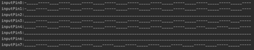
for i in range(0, 8):  # loop to iterate through the channels
    print("inputPin{}:".format(i), end='')  # print the input pin label
    for j in range(0, 99):  # loop to iterate through the samples
        if Dstore[i][j] == 0:  # check to see if the sample is low
            print("_", end='')  # print _ if it is low
        elif Dstore[i][j] == 1:  # check to see if the sample is high
            print("-", end='')  # print - if it is high
    print()  # print a new line after each channel
print()  # print a line in between each group of inputs
So by now, if you’ve read this through, we know how to print the values and how to use for loops. We are using the same concept here but for printing to the REPL. We are accessing both dimensions of the Array in the forth line and 6 line of code above to check to see if the sample we recorded was high or low, the REPL will then print out the waveform.
Conclusion
So there we go, a nice simple logic analyzer on the Pi Pico, great for debugging and monitoring digital lines. If I think of any more features to add then I’ll update this post, if you think of any and think I should add them then please comment below. Thank you for reading this and I hope you have learnt some extra things about the Pi Pico and Python along the way. Happy debugging.


